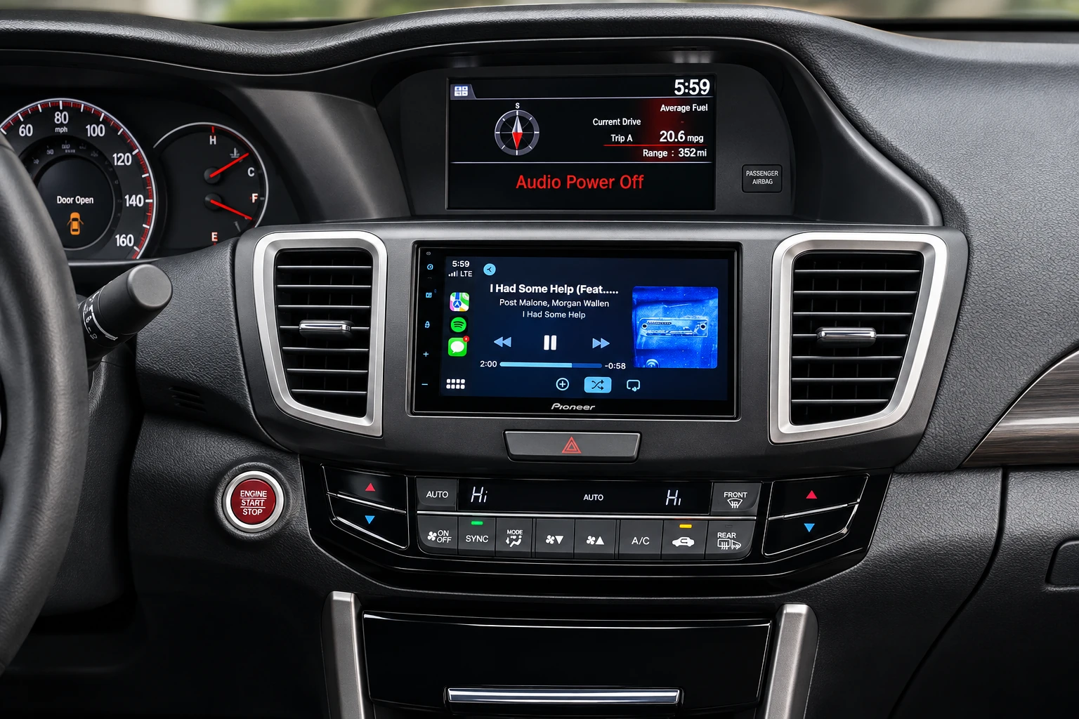

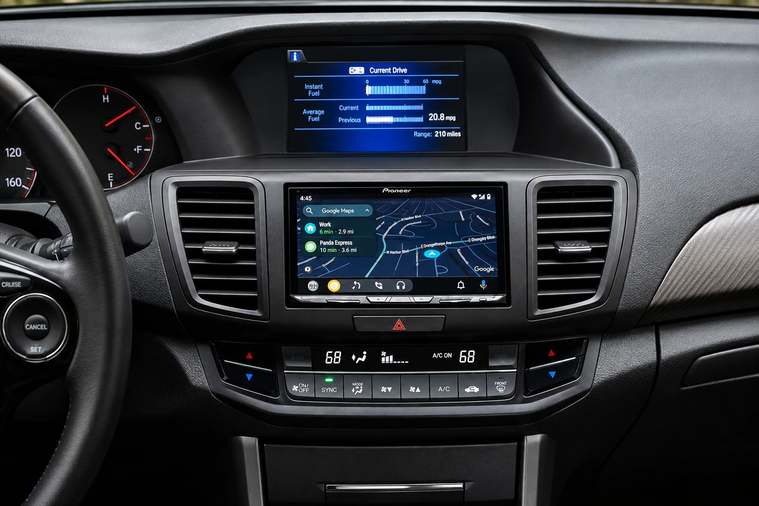
Check your Accord’s model year, trim, factory navigation/audio equipment, and the exact ExGP harness configuration. The photos are from ExGP kit manuals and may show different factory-radio variants. This work includes vehicle trim removal and modifications to interior plastic or radio hardware; avoid cutting or disconnecting components unless you have confirmed the correct procedure for your vehicle. Never power exposed electronics while handling or modifying circuit boards.
The 2013-2017 ExGP 9th-generation kit manual establishes the shared disassembly, bypass-harness, and wiring process. This article focuses on the common LX/Sport-style 2013-2015 route and links to the exceptions for EX-L touchscreen and later revised radios.
Which installation path applies?
This is the standard 9th-generation bypass-harness procedure shown in the ExGP 2013-2017 manual, particularly useful for the 2013-2015 LX/Sport-style factory head unit. The manual covers a broader model range, but radios and connector arrangements vary by year and trim.
- 2013-2015 LX/Sport-style non-navigation radio: continue with this guide after confirming fitment.
- 2013-2015 EX-L non-navigation touchscreen: use this guide for the common trim-removal, harness, and wiring steps, then follow the EX-L premium audio supplement for radio reduction and initialization.
- 2016-2017 revised head unit: follow the 2016-2017 guide for the different reduction/shield and initialization procedure.
Set the factory system before removal
The factory faceplate may be difficult to reach afterward, so set clock, audio presets, Bluetooth, and system preferences first. Where supported, the manual describes System Settings → Others → Header Clock Display → Off ; skip that change on a factory-navigation radio. An optional main clock setting is Info Settings → Clock Wallpaper/Type → Clock → Off .
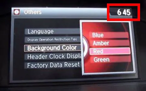
Unpair your phone from the factory HandsFreeLink Bluetooth connection and turn off factory Bluetooth to avoid competing reconnections. Turn the factory radio off and confirm the upper display shows Radio Off before disassembly.
Identify the bypass harness and connections
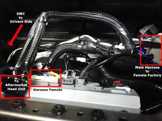
The ExGP bypass harness retains connections to the factory head unit while routing the required circuits to the aftermarket radio. Its exact adapter connector can vary by kit configuration.
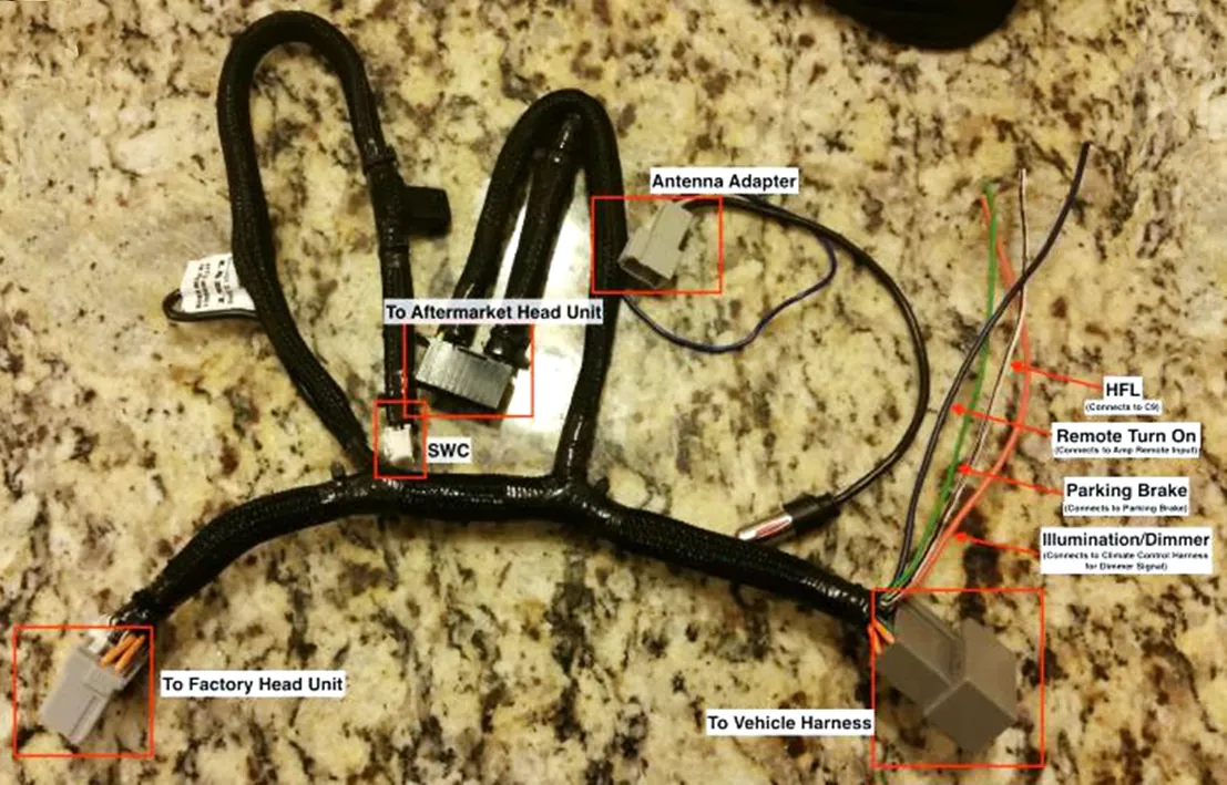
| Lead / interface | Purpose in the manual |
|---|---|
| Main factory-radio and vehicle plugs | Connects the factory head unit to the original vehicle wiring through the bypass harness. |
| Aftermarket-radio connector | Connects to your new head unit; plug configuration varies. |
| SWC | Steering wheel controls through PAC SWI-CP5 or Maestro SW, programmed using that module’s own instructions. |
| HFL (white/black or pink/red) | Phone-button signal from vehicle HFL wiring; do not reconnect the specified HFL harness to the factory radio. |
| Remote turn-on (blue) | Low-current trigger for external amplifier or DSP. |
| Parking brake (when supplied) | Connect only as directed by the aftermarket head unit’s manual; do not bypass driving-related interlocks. |
| Illumination (orange or yellow/black) | Connect to the specified climate-control illumination lead. |
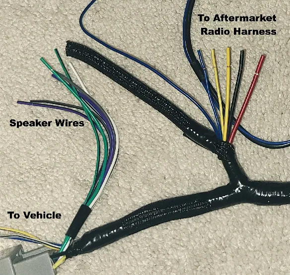
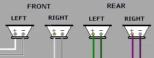
Harness output reference: red = switched 12 V ACC, black = ground, yellow = constant 12 V, blue = amplifier remote . Speaker pairs: white/front left, gray/front right, green/rear left, purple/rear right; black-striped wires denote negative in the illustrated harness. Confirm any variation against your physical harness.
Remove console trim and factory radio
The manual lists Phillips and flat screwdrivers, trim-removal tools, an 8/10 mm socket/extension, wire strippers or pliers, and a utility knife. Protect interior trim as you work and keep fasteners organized.
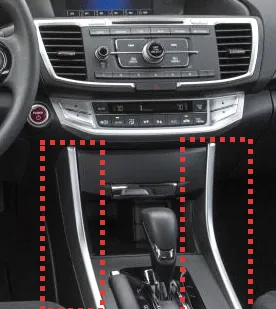
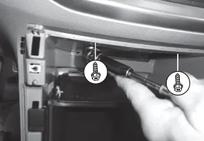
- Remove the console-side trim pieces and center console pocket.
- Remove the upper receiver trim and receiver-side panel.
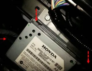
- Remove the upper and lower head-unit fasteners.
- Remove the illustrated ANC bolts and carefully withdraw the factory receiver.
- Remove the USB/accessory power trim panel to access the pocket opening.
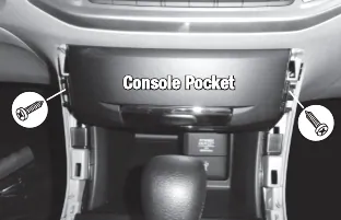
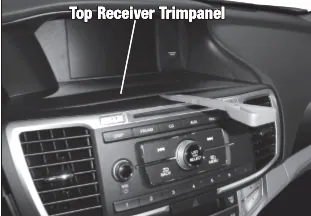
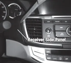
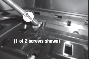
Prepare the pocket and factory head unit
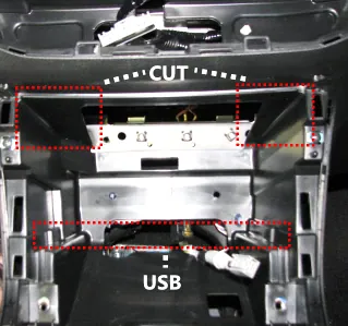
The manual shows trimming the USB/accessory pocket support to provide room to slide the original receiver behind the dash. This is an irreversible interior-plastic modification ; use the marked source photo only after confirming it matches your dash.
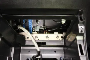
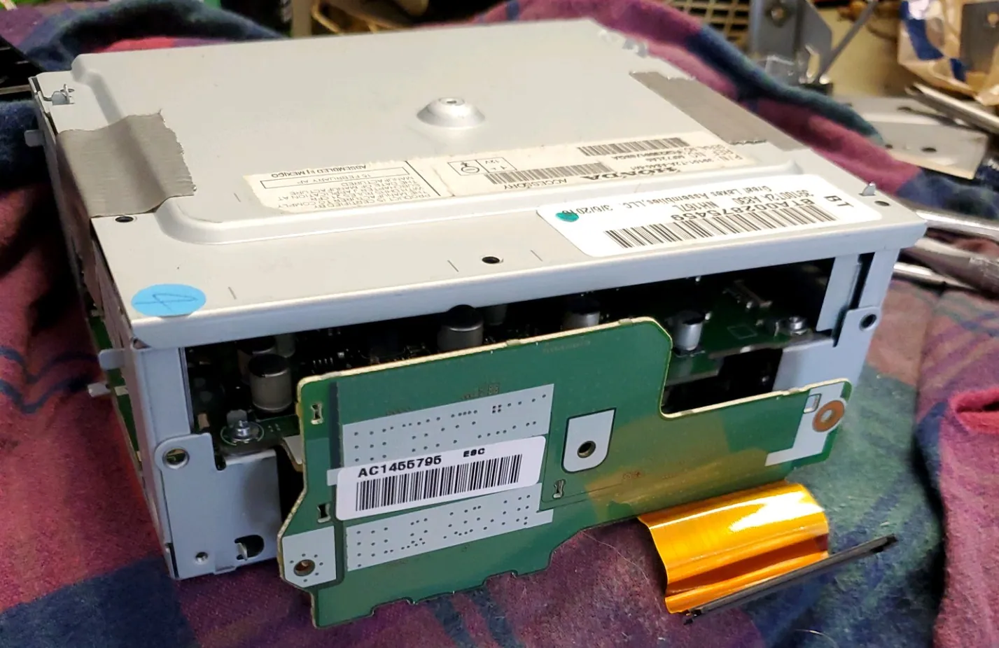
On the standard radio, remove the mounting side brackets and the factory faceplate screws. The aim is to reposition the retained receiver lower inside the dash, freeing the upper opening for the aftermarket unit. The manual also illustrates optionally retaining only the original button assembly.
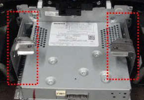
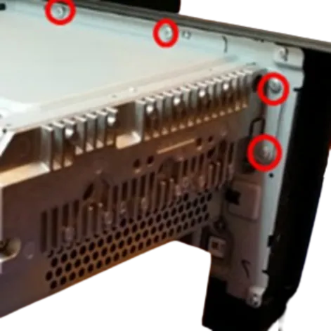
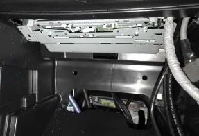
Do not apply the standard faceplate-reduction sequence blindly to the 2013-2015 EX-L non-navigation touchscreen radio. Its IC card and attached ribbon must stay in place. Follow the EX-L supplement instead.
Connect and position the bypass harness
- Feed the retained factory receiver upward through the enlarged center pocket opening behind the climate-control area.
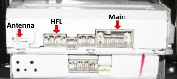
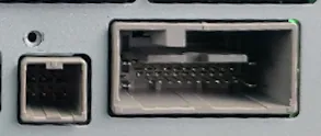
- For the standard arrangement, connect the factory plugs except the Main, HFL, and Antenna connectors reserved for the bypass/adapters, as shown in the manual. For EX-L the manual calls out a different exception: Main and adjacent subwoofer header .
- Connect the ExGP harness to the factory Main socket, then to the steering wheel control module, then to the vehicle’s matching plugs. Route the loom without pinching wiring or blocking trim.
Illumination and HFL wiring
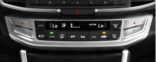
Remove the climate-control panel to reach the illumination lead. The manual identifies the middle gray wire at Pin 7, between green and orange wires , for the ExGP orange or yellow/black illumination lead. Route the lead underneath the metal frame so it does not interfere with the trim installation.
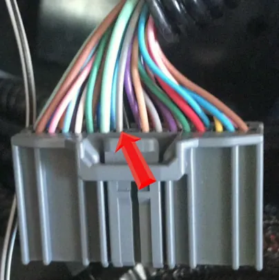
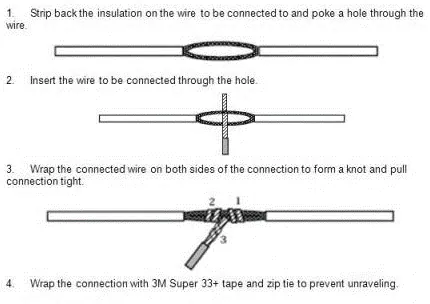
The manual illustrates a military splice for connecting the specified leads. Use an appropriately insulated, mechanically secure connection; the photo is not a substitute for identifying the correct wire on your specific vehicle.
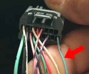
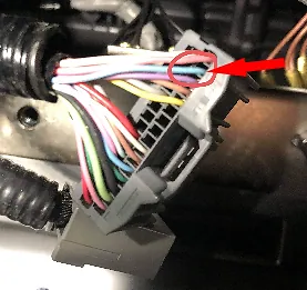
Connect the ExGP white/black or pink/red HFL lead to the factory harness’s light blue signal wire. The manual identifies Pin 9 on the 16-pin plug , or Pin 15 on the 32-pin plug when the vehicle uses the external Bluetooth module below the radio. The specified HFL plug must not be plugged back into the factory radio.
Finish and verify the installation
Complete the aftermarket radio’s power, speaker, antenna, microphone, RCA, amplifier, and steering-control connections using that equipment’s manuals. Before closing the dash, verify the original upper display, climate controls, new receiver, steering-wheel buttons, and any supported vehicle features. Confirm that wiring cannot be chafed, strained, or pinched by reassembly.
If you need to access the standard factory receiver later, the original ExGP manual describes removing the center pocket/USB trim, gently lowering the hidden receiver, temporarily reattaching its original faceplate, making adjustments, then turning the vehicle off and hiding it again. EX-L owners must follow the specific power-retention rule in the EX-L guide.
For kit/fitment help: [email protected] .